Portfolio Details
- Categories Autonomous Accessories
- Tags CELL LOAD, LOAD CONTROL, LOAD SENSOR, PESACARGAS, VK3
- CountryCanada
-
Description
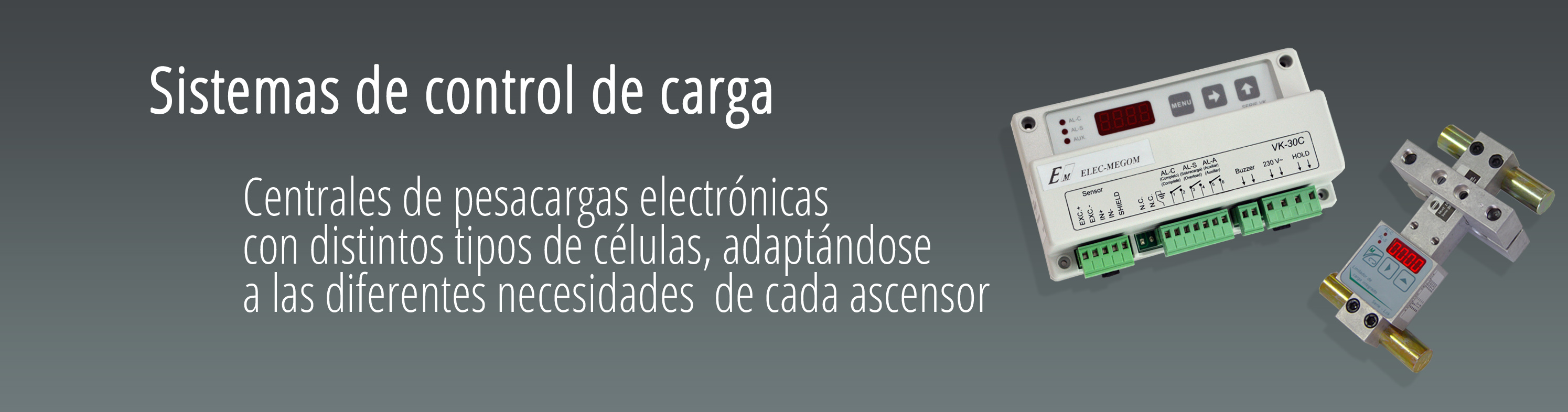
- Load control systems to ensure that the elevator will only operate when the load level for which it was designed is not exceeded, avoiding overloading the motor or the traction unit.
- Different systems for calculating the load in the cab, cells on the engine bed, on the traction cables, under the cab, each of them adapted to the needs of each installation.
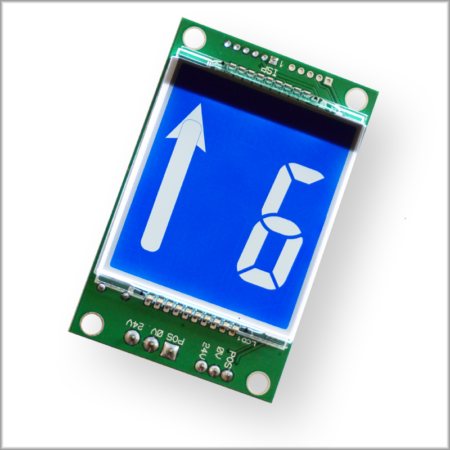
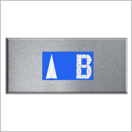
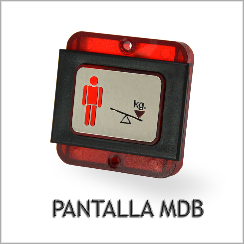
- The 10-division display informs the persons in the cab of the load status in relation to the permitted load.
Central models
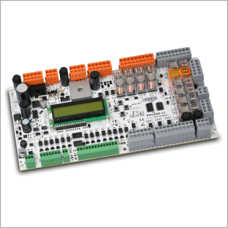
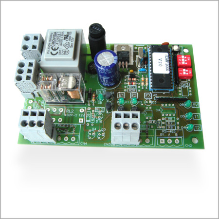
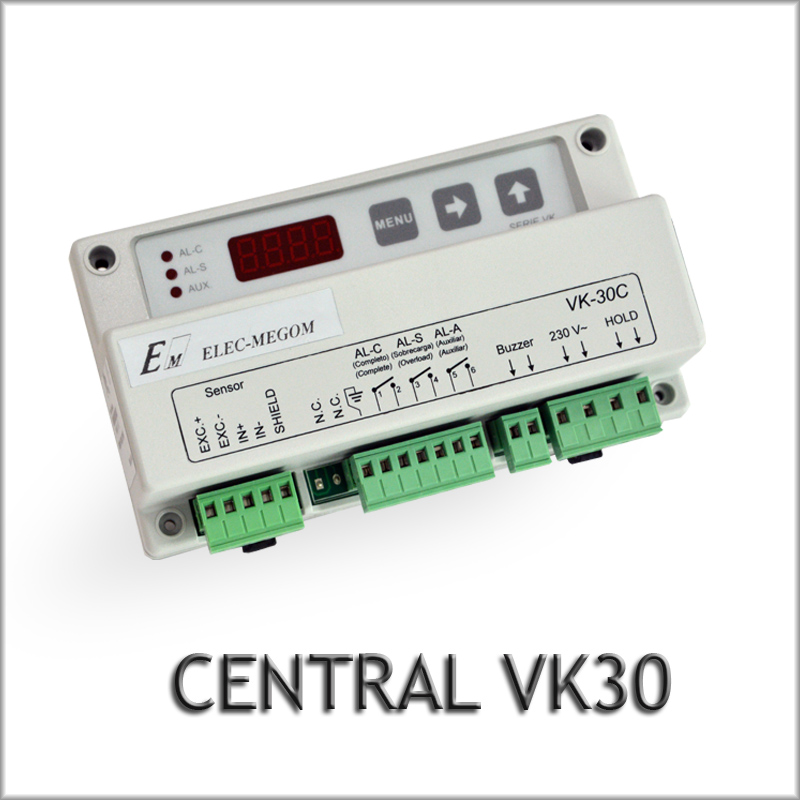
- VK30 load control unit, installed next to the load cell, depending on the load cell model, it will be installed in the cabin or in the machine room, it has 3 alarms, voltage free contacts, 230Vac power supply, inhibition signal input so that the measurement does not oscillate on the way and output for the MDB ramp, compatible cell types:
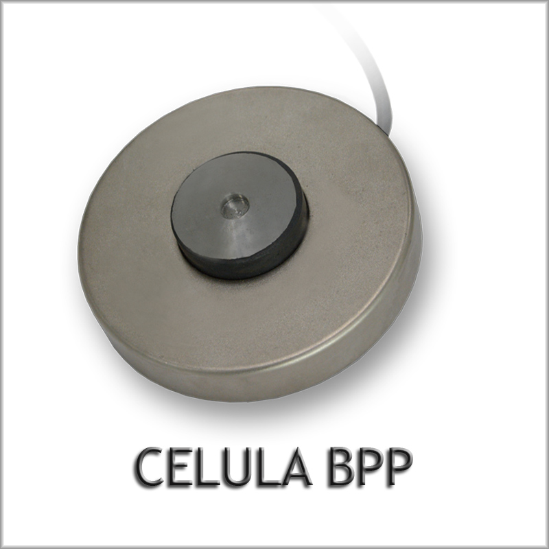
- BPP Cell (Benchtop)
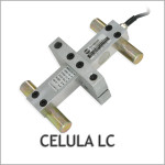
- LC cell (For the pull-wire assembly)
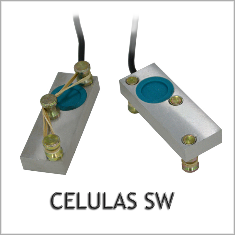
- SW Cells (For individual traction cables)
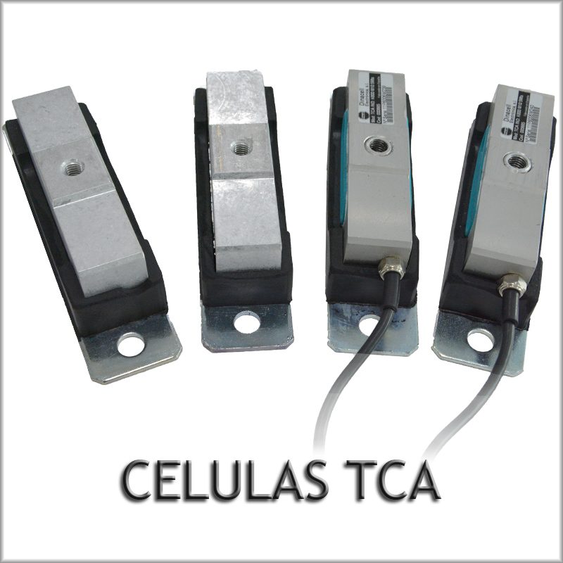
- TCA cells (installed under the cab)
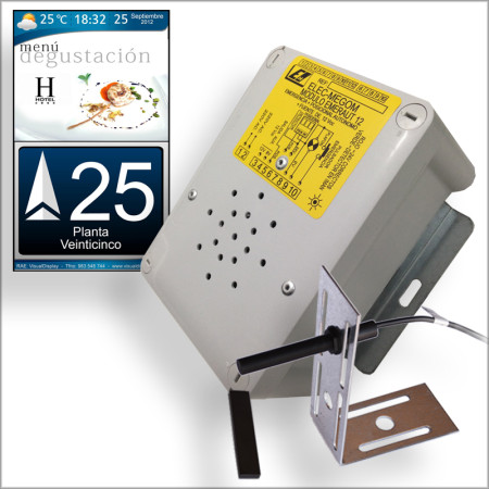
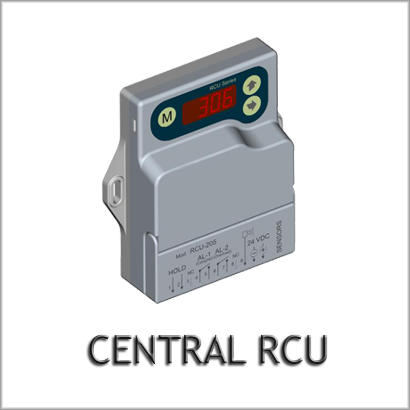
- RCU load control unit, installed next to the load cell, depending on the load cell it will be installed in the cabin or in the machine room, it has 2 alarms, voltage free contacts, 24Vdc power supply, inhibition signal input so that the measurement does not oscillate on the way, it does not have an output for the MDB ramp, but it does include a 24Vdc output to connect a buzzer in case of overload, the compatible cells are the same as for the VK30.
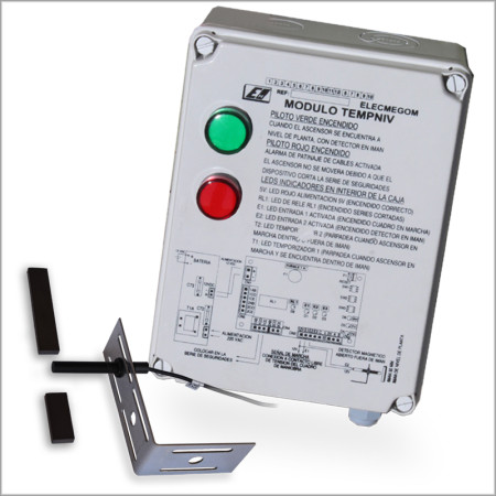
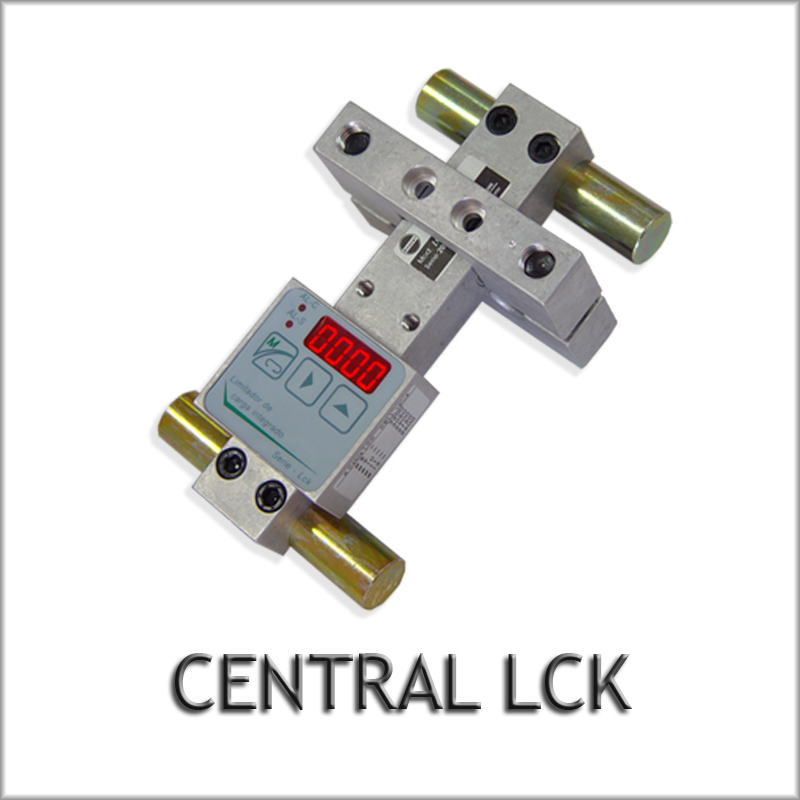
- LCK load control center, installed in cab with integrated load cell, which makes it the most competitive and easy to install model, it has 2 voltage-free alarms, 24Vdc power supply, inhibition signal input so that the measurement does not oscillate on the way.
Cell models
- BPP cell, installed on the machine bed as a silent block
- LC cell, installed on the traction cables, a single flange for any number of cables in the elevator, capacity up to 3000 Kgs. For elevators up to 8 cables, with cross sections between 3 and 18mm.
- SW cells, set of individual cells to be placed on each of the traction cables, installed in the cabin, supplied in groups of 2 or 3 cells.
- Set of TCA cells, to be installed under the cabin as a silent block, 4 cells are supplied, calibrated so that weight adjustment is not necessary, the four cells can be active or 2 active and 2 passive.
Others
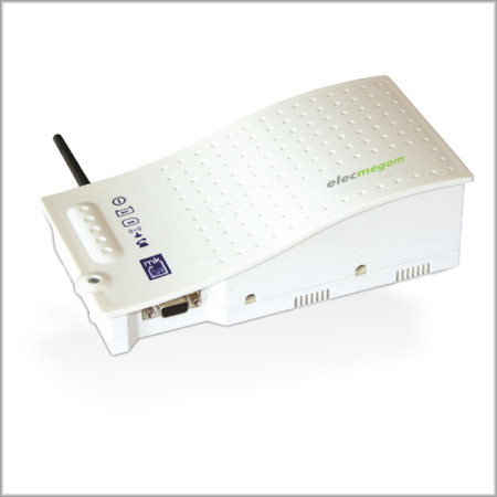
- Display of MBD load status, information of the cabin load by means of 10 luminous divisions, once the allowed load is exceeded, it illuminates an overweight signal, besides indicating the overweight status by means of an intermittent buzzer, it communicates by means of two wires with the load weighing control unit, it is compatible with the VK30 module.
For users of this product we provide a complete guide in different languages. Click on the flag icon corresponding to the language you wish to download.
Description |
Spanish |
Francaise |
Español |
|
Installation Manual VK-30 |
|||
|
LCK Installation Manual |